The corrected beam from the AO system will feed a spectrograph through an IFU conformed by a lens let array+fibers with the peculiarity of regulating the output intensity of the central seven fibers. In this way, the contrast between the bright object and its surroundings will decrease allowing the detection of closer object/structures, obtaining the maximum spatial resolution and minimum contamination of the surroundings from the brightest object.
 |
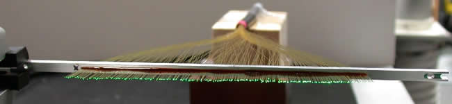 |
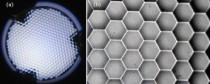
In order to test variable attenuators we acquired a bundle (EB#1) in which 7 fibers include variable attenuators. EB#1 also has 331 fibers in a similar hexagonal configuration than the EDiFiSE EIFU but without lens lets. The EB#1 was built by FiberTech Optica Inc. in Canada. As soon as the EB#1 is characterized it will be installed in INTEGRAL (Arribas et al. 1998, SPIE, 3355, 821) and we will obtain observations (seeing-limited) of high-contrasted objects at the 4.2mWHT. (left) EB#1being illuminated by light shining down the fibers from the fiber slit. (right) Slit view, showing the linear alignment of the fibers at the slit before its polishing.
|
|
of the Equalized Integral Field Unit
•Lens array → It is a monolithic piece of 11.63 mm of thickness
- 331 hexagonal elements in an hexagonal configuration
- It was made from fused silica, also in an hexagonal configuration
- Each lenslet is 1mm in diameter, with a curvature radio of 3.627 mm
- The output f-number of lens lets is 8
- common-plane back side where each fiber is attached
- It has been manufactured by Advance Microoptic Systems GmbH.
•Fibers → To re-arrange the 2D information sampled by the lens array onto a linear pseudo-slit. Our fibers are from Polymicro, type FBP050070085. Each fiber is 2 m long. They are multimode, silica core, doped silica clad, with numerical aperture of 0.22. Core diameter of 50 µm and a clad/core ratio of 1.4.
•Variable attenuators → Electrically controlled variable neutral filter attenuators that can reduced the input light to the desirable level. See (2)
•Slit → Fibers are arranged linearly at a distance of 177.5 μm. This guarantees that the spectra are well separated on the detector, reducing the cross-talk. This pseudo-slit constitutes the entrance of the spectrograph.
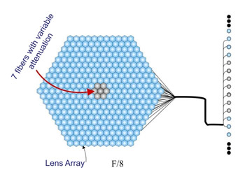 |
Sketch of the EDiFiSE IFU. The 331 lens lets present an hexagonal configuration at the focal plane of the telescope, while these spaxels are linearly aligned at the spectrograph entrance forming a pseudo-slit. The central seven spaxels include commercial variable attenuators to control the light passing through them.
|
.
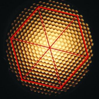 |
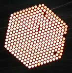
The micro lens array built for the EDiFiSE IFU. The red hexagonal corresponds approximately to FOV.
|
| Principle of operation | Hexagonal lenslet array + fibers |
| Lenslet array | 331 hexagonal elements, 1 mm pitch |
| Num. of fibers with variable attenuators | the 7 central fibers |
| Attenuation range and temporal stability | 0-100 % and 6 hours |
| Pre-optics magnification | 0.3 arcsec sampling |
| FOV | ~6.5 arcsec in diameter |
|
|
||
|
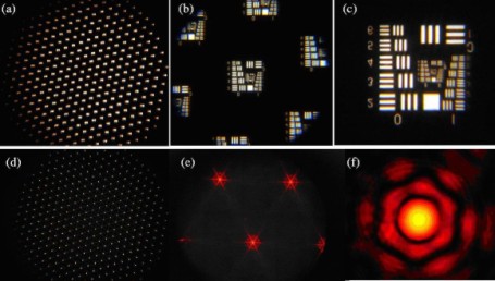
Characterization of the lenslet array
 |
(a) Image of the full lenslet array. (b) Detail of the surface of the lenslet array. Note the gaps between lenses and the annular pattern due to the manufactured process.
|
.
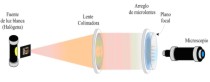 |
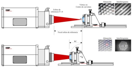
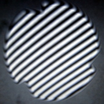
Optical setup used to test the resolution provide by the lenslet arrays. In the case of image quality, the extended source was changed by a pinhole.
|
| Requirements of the lenslet arrays acquired for the EDiFiSE integral field unit in comparison to the measurements determined at the laboratory | |||
Required |
Lenslet Array #1 |
Lenslet Array #2 |
|
| Material | fused silica (n=1.45332, wl=800 nm) |
OK |
OK |
| Thickness | 11.63 mm |
11.645 mm |
11.623 mm |
| Shape / size | Circular / 25 mm |
24.85 mm |
24.97 mm |
| Distribution | Hexagonal |
OK |
OK |
| Number of lenses | 331 |
OK |
OK |
| Lenslet shape | hexagonal |
OK |
OK |
| Space within lenses | 0 mm |
. |
. |
| Lenses focal ratio | F/8 |
8 |
8 |
| Lens type | plane-convex |
OK |
OK |
| Optical aperture of lenses | 1 mm |
1 mm |
1 mm |
| Lens curvature radio | 3.627 mm |
3.631 mm in average |
3.59 mm in average |
| Effective focal length | 8 mm |
8.0 mm in average |
7.92 mm in average |
| Antireflective film | both sides |
OK |
OK |
|
|