
The following were correct as of Aug. 2004. These pictures are more FYI, as all these connections are made by the ING staff; indeed you should not do anything without first getting permission.

The following were correct as of Aug. 2004. These pictures are
more FYI, as all these connections are made by the ING staff; indeed you
should not do anything without first getting permission.
![]()
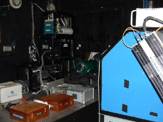
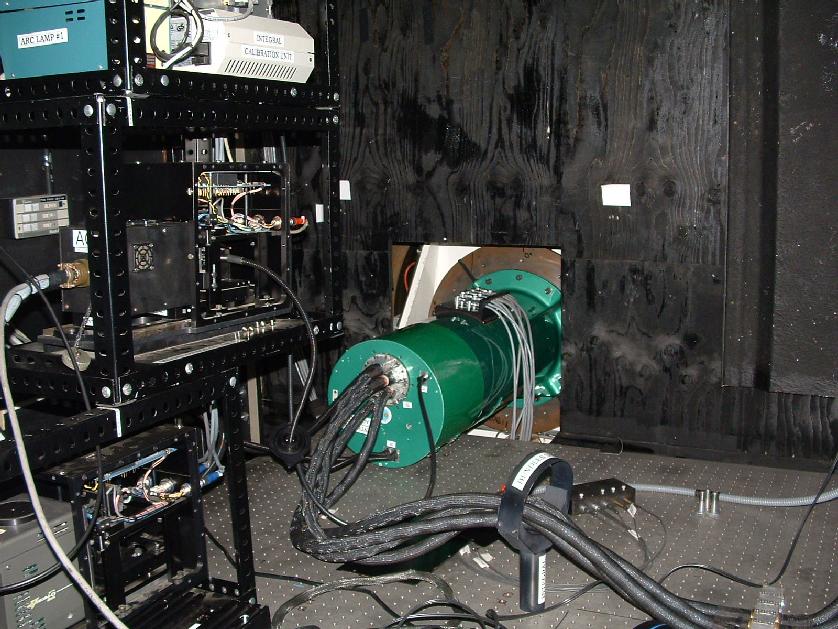
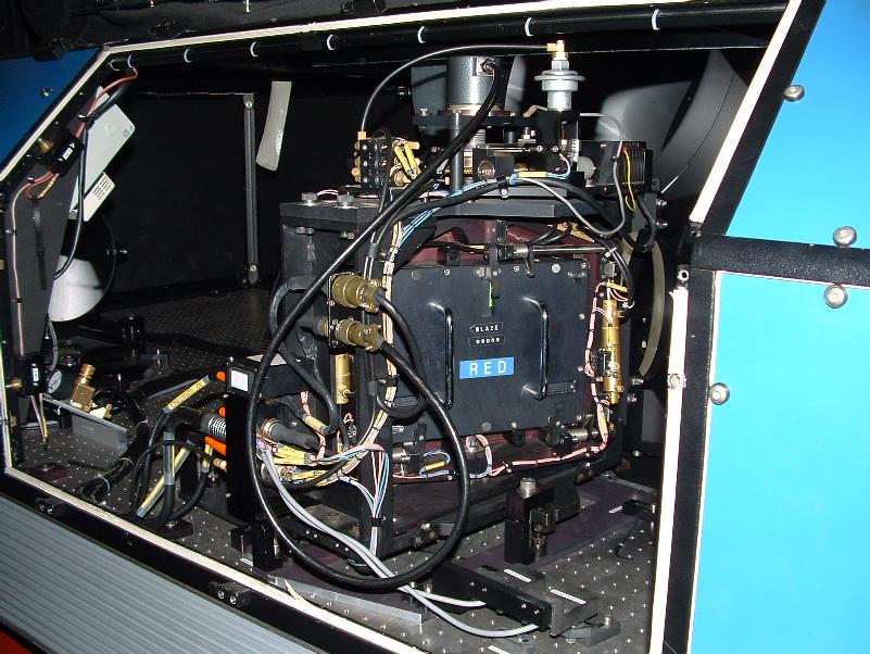
Inside GHRIL, with WYFFOS on the right and INTEGRAL (green) in the middle.
Integral (green) with the fibre bundles (black) going to WYFFOS, grey cables
going to the power units (out of view), and the rig containing all the other
bits and pices.
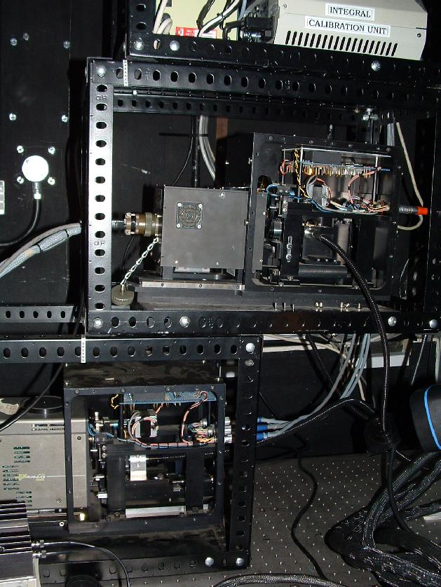
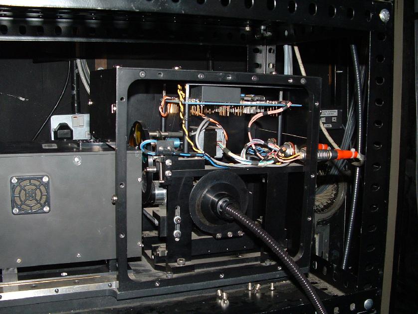
The rig holding INTEGRAL; the acquisition camera on the bottom left, the
guider camera in the middle, and the arc/white lamps top right.
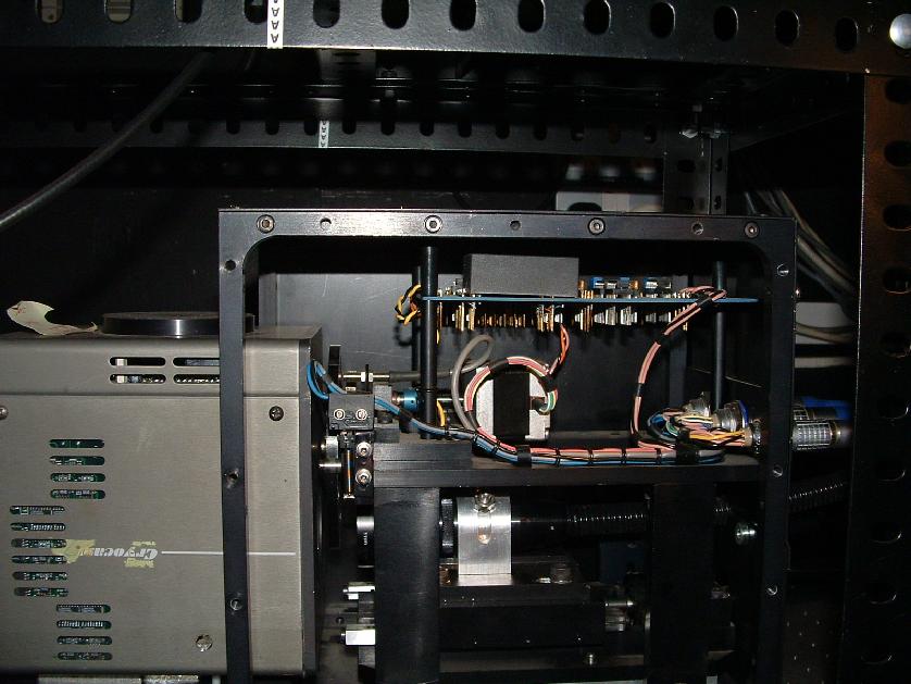
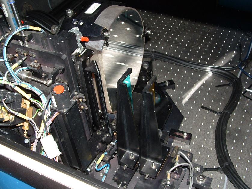
Close-up of the acquisition cameram as of Aug. 2004; it may have changed since then.
Close-up of the autoguider unit, which also may have changed since Aug.
2004. You can see the feeds from one of the two fields-of view.
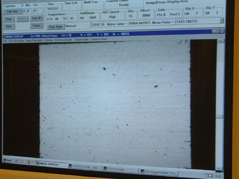
A picture of what you see on the computer display when adjusting the focus of
the acquisition bundle.
The grating unit, with the two metal bar-connectors ("reflection" and "echelle"
are written on them). Here it is in reflection mode.
The two filters in place, with B being on the left.
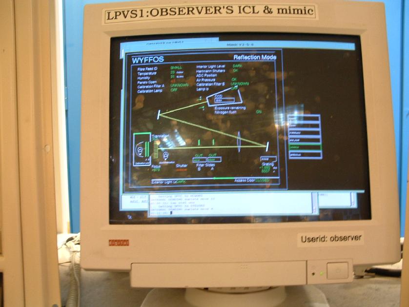
The display showing the mimic for WYFFOS and INTEGRAL (and others), being the
terminal you change wavelengths, grating information, focus, etc on.
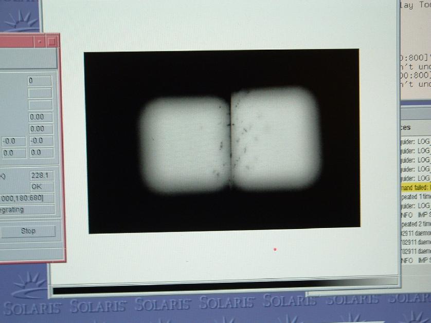
A (rather fuzzy) picture of the image that comes out of the two guider
cameras, and what you should see as you are focusing them.
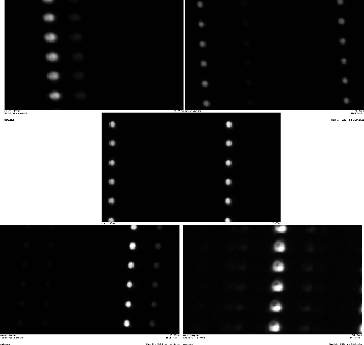
An image of a flatfield, with fibre bundle STD2.
An image of an arc with STD2 and the 1200 g/mm grating, showing the change of
the fwhm of the arc lines on the different
parts of the 2-CCD (not yet very well focused). Position of the individual
images is representative of the position on the 2-CCD plane.
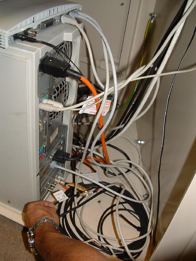
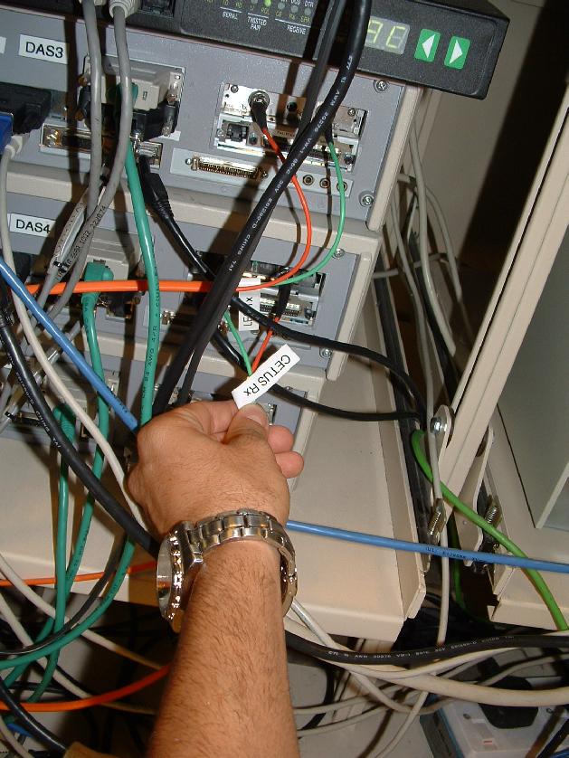
Computer connection, in panels just behind where the terminals are in the
control room. Attach cable with GHRIL written on it to whichever computer
(eg WHTDAS4) is to be used.
The green light must be on on the CETUS computer (or whichever is to be used
if CETUS is no longer). This is in another panel just behind where all the
terminals are (ie. where the observers sit), to the right of the previous
computer. Left picture shows the green light, right picture a pull-out view.
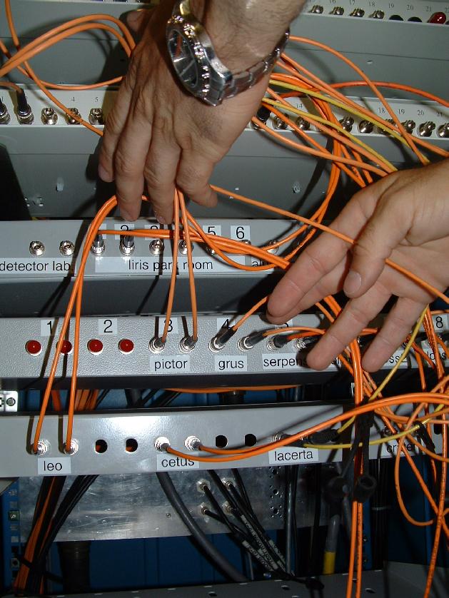
Connections to make in blue cupboards at back of control room also. It is the
first row of cupboards, on the very right as you look at them. These are the
CCD connections. Connect CETUS (shown here) at one end to position 13+14
(GHRIL 3 and 4) on one of above boxes of connections. These are the AG CCDs
(FYI: 11 and 12 are the cryocam CCDs). If this does nothing, try swapping the
two around from the (left-right) order they were in when you first connected
them.
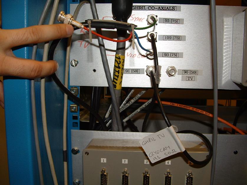
More cable connections. In the blue cupboards on the other side of
the previous one, again
you want the GHRIL cable connected, to "91", as is shown here.
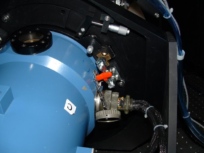
Capstan C. Note that there have been some changes to the CCD since this photo
was taken.