Stage II Result (Engineering Detector NIR)
The goals of this stage was:
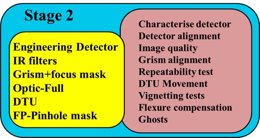
In this stage we had the finally configuration of the instruments (except the CSU) and using the engineering detector similar to the science detector and the pinholes mask in the focal plane. We also had the whole control system ECS (including the DRP).
The results, can be summarised as follows divided in two sub-stages: Stage IIA with the new pinholes mask (see figure); Stage IIB with the focal plane open.
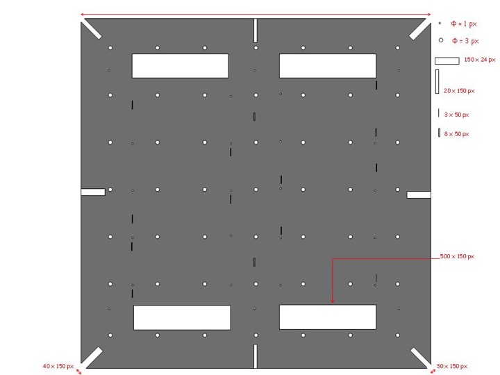
Stage IIA:
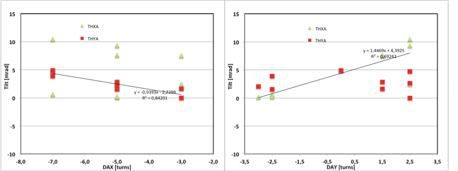
- There are a small tilt between the detector-focal plane. The angles of a fitted plan in mRad were 1.567+/- 0.65 and 0.58+/- 0.65 in X and Y axis respectively.
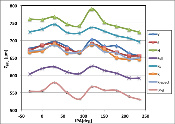
- We had measure the best focus for each filter (Y, J, H, K, K-short, K-spect, Brackett-gamma and FeII).
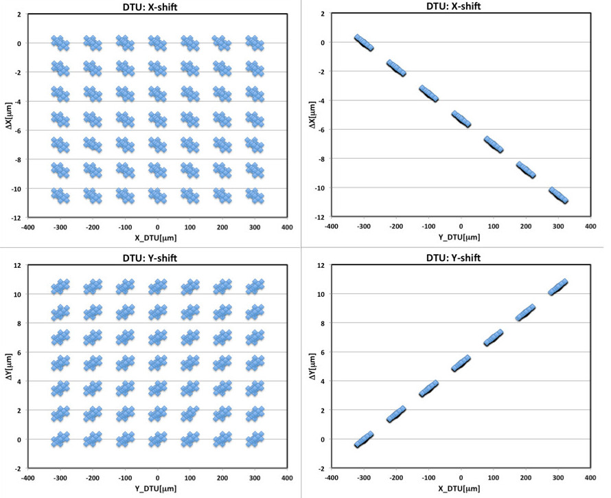
- The DTU has an accuracy better than the specifications. We have measure the precision and repeatability in different orientations of EMIR. There is a sistematic error in the measurements dominating the results. This effect will be negligible when a correction factor is introduced, around 0.99. This factor is due to the difference between the operation temperatura (95K) and the calibration temperatura (83K). The average errors are lower than 10-3 μm.
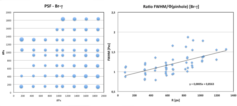
- The image quality has been checked: distortion of 1.61%; FWHM of 1.39 +/- 0.29 px (using the 1 px pinholes of the mask); and plate scale of 0.192 arsec/px.
- All the mechanisms works correctly.
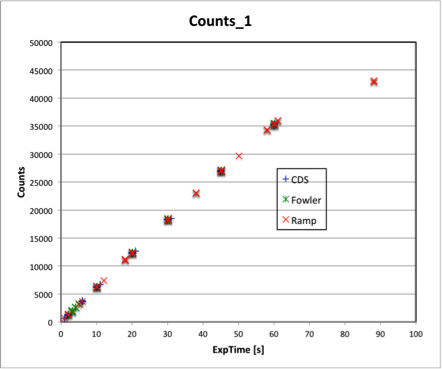
- All the EMIR readout modes works and are photometrically compatible: SIMPLE, CDS, RAMP and FOWLER.
- There are not scattered light in preliminary test (with the mask in the focal plane).
- The DRP integration have been successfully.
- The control system was yet in a preliminar phase.
Stage IIB:
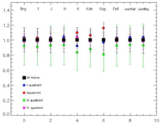
- The flat field images are homogeneous for each filter. The figure shows the median value of the flat-field images in each filters in the diferent quadrant of the detector.
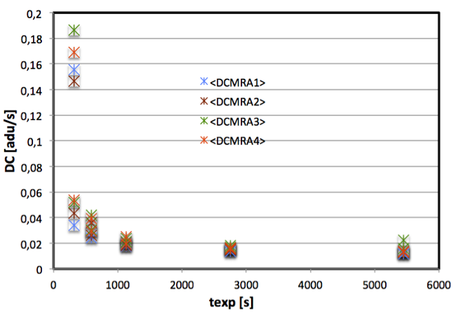
- The dark current (DC) of the engineering detector has been checked. The DC reach a stable value in times of 3000 s.
- The filter and grism wheels move and are positioned correctly.
- The spectra have been aligned correctly along the detector.
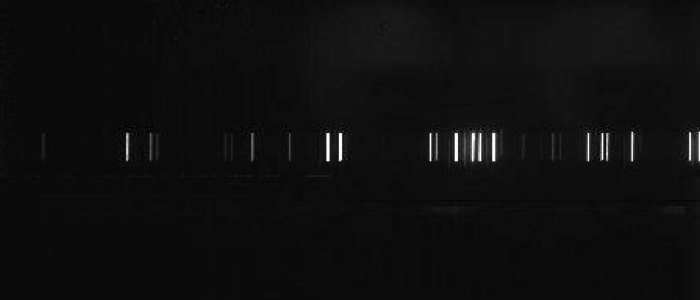
- The spectral range is verified: 0.9-2.5 µm.
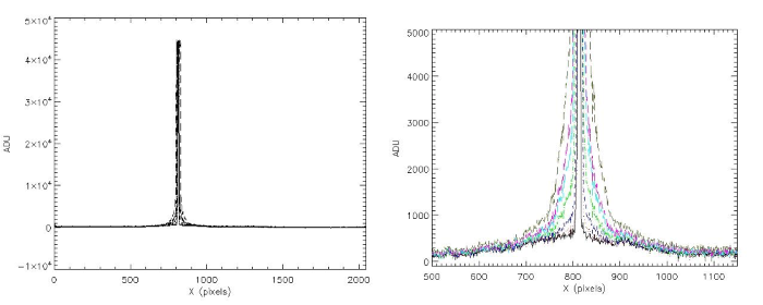
- There are not scattered and diffuse light. A long slit was used to test the light and the figure shows that the light fades fast in the regiones out the slit.
- There are not ghosts in the images. Ghosts have not be seen in any of the zones of the detector when we illuminate enough to reach the saturation level or to vary the position of the illumination pattern.
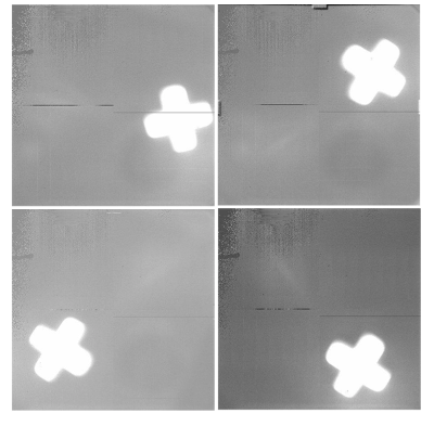
- There are not any physical element blocking the field of view.
- The grism dispersion and resolution obtained are compatible with the requirements.
| Grism | λc (Å) | Dispersion (Å/px) |
Δλ(Å) |
| J | 12530 | 0.771 | 11741-13318 |
| H | 16460 | 1.216 | 15210-17709 |
| K | 22000 | 1.710 | 20269-23730 |